Series Circuits
Current, voltage, equivalent resistance, and power in a single-path circuit
|
APlus Physics YouTube Channel
Show Me The Physics
H) Series and Parallel Circuits
UC Irvine
Why is it a good idea to connect
Circuits Show Me The Physics
Which kind of circuit do we have below? Video on Circuits
Series
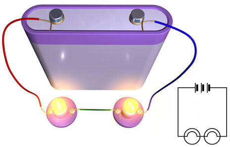
1) Series Circuit - circuit that has only one current path
Dorling Kindersley Books
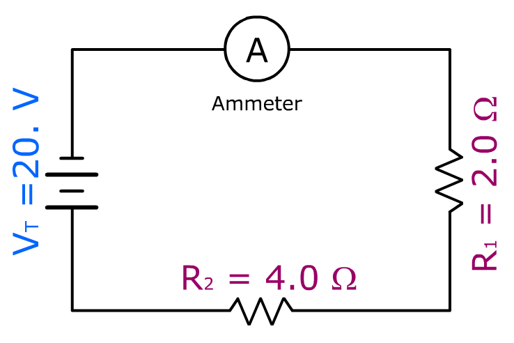
Ex 1) Ammeter – Meter that measures Current
Reference Table Equations
a) IT = I1 = I2 = I3 = ... Total Current
b) RT = R1 + R2 + R3 + …
RT = 6.0 ohms
c) VT = V1 + V2 + V3 + ……
d) VT = ITRT OR RT = VT/IT
Find total current (IT)
VT = ITRT
20. V = IT(6.0 ohms)
IT = 3.3 amps = I1 = I2
Name that Circuit
Show Me The Physics
School blocks YouTube? Use the file below.
|
|




Check Your Understanding
5 quick questions — pick an answer to see if you’re right.
1. A series circuit is a circuit that has:
2. Resistors of 2.0 Ω, 3.0 Ω and 5.0 Ω are connected in series. What is the total resistance?
3. A 12 V battery powers a 2.0 Ω and a 4.0 Ω resistor in series. What is the current?
4. In a series circuit with a 9.0 V battery, one resistor has a 4.0 V drop. What is the drop across the only other resistor?
5. Old holiday lights were wired in series. When one bulb burned out, what happened?
A String of Decorative Lights
Three bulbs with resistances of 10. Ω, 20. Ω, and 30. Ω are connected in series to a 12-V battery.
What is the current in the circuit?
▶ Want a challenge? Open 6 more Regents-style questions (harder · mixed formats)
Challenge score: 0 / 6
C1. Substitute numerical values into a mathematical representation that can be used to determine the potential difference across the 20.-Ω bulb. Then calculate the potential difference.
C2. One bulb burns out (its filament breaks). What happens?
C3. A student makes the following claim.
Place a check mark in either the Support or Refute box. Justify your response using a mathematical relationship.
C4. Determine the electrical power used by the 30.-Ω bulb.
C5. Which statement about the potential differences in the series circuit is correct?
C6. The 10.-Ω bulb fails in a way that leaves a wire connection (zero resistance) in its place, so the other two bulbs stay lit. Describe what happens to the brightness of the 20.-Ω and 30.-Ω bulbs, and support your answer with a calculation.